
We recently brought back our original Nugget soldering kit, allowing beginners to make their own Wi-Fi, USB, or prototype Nugget boards.
If you have one, here's a guide to putting it all together!
You can also check out this video guide:
First, you can put together two different types of Nugget builds with this kit. Let's take a look at the difference between them:
Option A: Build a standard Wi-Fi or USB Nugget

For this option, we'll follow the steps to make either a USB Nugget or a Wi-Fi Nugget. After we're done, we'll have a leftover microcontroller from whichever one we decided not to make.
Option B: Build an OmniNugget & swap between Wi-Fi and USB Nuggets
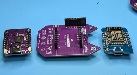
With a tradeoff of being thicker overall, you can solder female pin headers to the back of your Nugget instead of a microcontroller, allowing you to swap between plugging in the D1 Mini and S2 Mini boards.
Once you've decided which you want to make, we can get started with assembly!
Included in each kit:
- One Nugget PCB
- One SH1106 screen
- Four buttons
- One neopixel
- Eight Pin headers
- One D1 mini esp8266 microcontroller
- One S2 Mini microcontroller
- One 3d printed Nugget case
Omni-Nugget Assembly:

A thicker board that allows for swapping between the D1 Mini, S2 Mini, and S3 Mini. The C3 Mini is also supported but not included.
1) Solder the buttons and neopixel to the front of the board.
Make sure to orient the indent in the corner notch in the neopixel to align with the marking in the PCB so it's oriented the right way. Try to be careful around the neopixel and avoid melting the plastic.
2) Solder in microcontroller pin headers
If making a USB Nugget or BLE Nugget, solder short female header pins to the 2 inside rows of the S2 Mini board.

You can use 2 male pin headers to help hold these in place during soldering. Make sure to try and keep these straight! You can solder just one pin and easily adjust the angle, but once you solder more than one pin, it's hard to fix.
Next, solder male pin headers to your microcontrollers with the long side facing down (away from the main chip on the board). See photos below.


Make sure to keep these straight!
3) Solder in Female Pin Headers
On the side of the board that says "Solder me first," solder in 2 short female pin headers. You can plug them into one of the microcontrollers you just soldered to make sure they line up straight.

4) Solder the rear pin header breakout
Solder the female pin header to same side you just soldered the microcontroller. Try to keep this as straight as possible.

5) Add the screen
Finally, flip to the side that says "Solder me second" and add the SH1106 screen. Solder only 1 pin first and check to see if the screen is straight.
If it's not straight, melt the solder and adjust until it is before soldering the other pins.

At this point, your Omni-Nugget should is fully assembled!
Plug one of the included microcontrollers in and go to Nugget.dev in a Chrome browser to browse and flash supported projects.
The instructions for the standard Nugget are nearly identical:
Standard Nugget Assembly:
The slimmest Nugget build, but requires you to choose which Nugget you want to commit to. First, pick if you want a Wi-Fi Nugget, USB Nugget, or prototype BLE Nugget.
1) Solder the buttons and neopixel to the front of the board.
Make sure to orient the indent in the corner notch in the neopixel to align with the marking in the PCB so it's oriented the right way. Try to be careful around the neopixel and avoid melting the plastic.
2) Solder in USB Nugget pin headers (optional)
If making a USB Nugget or BLE Nugget, solder short female header pins to the 2 inside rows of the S2 Mini board. If making a Wi-Fi Nugget, skip to the next step.
You can use 2 male pin headers to help hold these in place during soldering. Make sure to try and keep these straight! You can solder just one pin and easily adjust the angle, but once you solder more than one pin, it's hard to fix.
3) Solder in your microcontroller of choice (D1 Mini, S2 Mini, or S3 Mini)
On the side of the board that says "Solder me first," solder in your microcontroller of choice with male pin headers. Make sure the long side of the pin headers are facing up towards the microcontroller, or they will poke through the PCB too far and hit the screen.

Make sure to orient the USB port to face the direction shown on the PCB. Do not get this turned around!
4) Solder the rear pin header breakout
Solder the female pin header to same side you just soldered the microcontroller. Try to keep this as straight as possible.
5) Add the screen
Finally, flip to the side that says "Solder me second" and add the SH1106 screen. Solder only 1 pin first and check to see if the screen is straight.
If it's not, melt the solder and adjust until it is before soldering the other pins.
Final step for both builds: Assemble the Case
Take the backplate from your kit. This is the part of the case that will hold your assembled Nugget.
Press your assembled Nugget into the backplate. It should fit snugly.
Now, find the D-Pad and the faceplate. The D-Pad is the directional pad, and the faceplate is the front part of the case.
Place the D-Pad into the faceplate, face down. This means you should be looking at the back of the D-Pad.
Finally, take your backplate with the assembled Nugget and flip it over. Snap this part into the faceplate to complete the case assembly.
How did your build go? Have questions? Join us on our Discord server and share!